In-probe receivers for medical ultrasound systems
Cardiovascular diseases (CVDs) are the leading cause of death worldwide with an estimated 17.9 million deaths per year, according to the World Health Organization (WHO).
There are two important steps when solving any problem: first, knowing there is one and, subsequently, finding out how to solve that problem. An example could be, in our case, having an electronic image of the heart and, through the analysis of doctors (cardiologists) or via artificial intelligence (AI), finding both the problem and solution.
A question which perhaps touches on science fiction: Can you imagine a world in which everyone has access to a hand-held portable ultrasound device with the capability of showing both the problem and solution, without having the need for any prior knowledge to interpret the result? Maybe you are wondering how this could be possible. How could such a high number of circuits be integrated into such a small device? This is where the art of electronics kicks in. This is one of the reasons why we are trying to integrate more and more electronics inside the probe (to keep the same requirements, but in a much smaller area).
Returning from the realm of science fiction: Every single day doctors try their best to save as many lives as possible, but sometimes, due to limitations in resolution, it is hard to predict the disease just by looking at an image of the heart.
So, knowing the problem, the question arises: how can we help the doctors to prevent CVDs in time? The solution is to increase the resolution of the heart imaging. But first, this method must be non-invasive!
How is this possible?
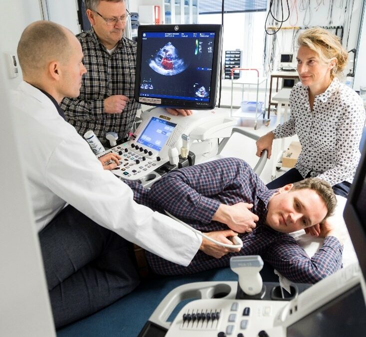
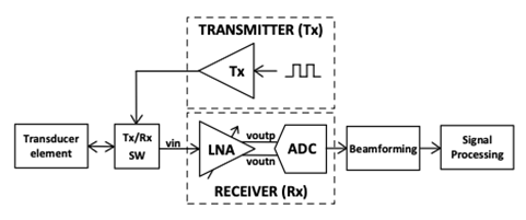
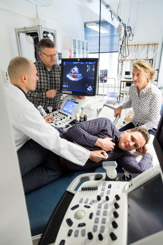
We can improve heart imaging by designing new analog circuits, which play an important role in the quality of the image, since the signal is processed by digital processing aided by artificial intelligence. So, the better we ‘translate’ the analog signal to digital signal, the better the digital processing. Figure 1 shows how an electronic heart image is created. There are three main blocks: the transducer, the electronics (Transmitter, Receiver, T/R switches) and the digital signal processing (Beamforming and Signal Processing). You may wonder where all these devices are placed. Usually, the digital processing and some of the electronics are placed outside of the probe. We aim to integrate more and more electronics into the probe (see the probe from Figure 2) without dissipating more power
Being passionate about electronics, my research stops at the first highlighted point: the electronics part of the block diagram. More precisely, my research is focused on the receiver part, on how I can improve this circuit to increase the quality of ultrasound heart imaging. Thus, many ideas and good technology are needed!
How can I improve the quality of the picture through the technology used?
Since we need to picture approximately 15 cm deep to obtain the heart image, our first care is to be able to still obtain echoes from that depth – since the signal is more and more attenuated while travelling through the body. But we also know that the attenuation is proportional to the frequency we use and as high as the frequency will be, so the better resolution we will have. This is the problem we encounter in ultrasound heart imaging: the trade-off between the wanted depth and the resolution.
Then, the question is, why can’t we just transmit to a sufficiently low frequency (to be able to picture at the depth of 15 cm) and receive at a high frequency? Thankfully, this idea pushed our research further and further, and the funny part is that it was discovered in the same way as other great ideas (e.g., the low of gravity – discovered by Isaac Newton) – by accident! This incident took place in the USA [1], where the researchers discovered a great improvement in the resolution of the picture by listening to a frequency twice as high as the transmitted frequency.
Knowing the piezoelectric transducers are suitable for low frequencies and that capacitive micromachined ultrasonic transducers (CMUT) are suitable for high frequencies, we will use both: the piezoelectric for the transmitter and CMUT for the receiver. This technology is called Dual frequency hybrid CMUT technology. Using this technology, we can improve the resolution, decrease the side lobes and artifacts effects.
How can I improve the quality of the picture through the design of the receiver?
You may wonder why the receiver circuit is necessary, as we are able to solve a lot of problems through digital processing? Valid question indeed, but first we need to convert this analog signal, received from echoes, into a digital signal, so we need an analog to digital converter (ADC). Can the signal received from the echo be sent directly on to digital processing (by using an ADC)? This is not possible because it brings loss of information since the signal is attenuated while travelling through the body. Therefore, the use of a time gain amplifier is also highly important in the receiver analog design circuit. Putting these two reasons together, it becomes clear why designing a receiver circuit is an important stage in improving ultrasound heart imaging.
So, the purpose of the receiver device is not only to provide the digital signal for processing without losing the information, but also to improve the quality of the ultrasound heart imaging by developing new integrated in-probe electronics using dual frequency hybrid CMUT technology, making it possible to improve the quality of the ultrasound heart imaging while keeping the same power dissipation. Having in mind both improving of the ultrasound heart imaging and a low power dissipation, we came up with a new idea of designing a low power low noise amplifier (LNA), using a common mode feedback circuit which ensures a single-ended to differential-ended feedback consumption close to zero (see reference [2]).
Stay tuned – new and updated information and ideas are on their way and will be written here!
References:
Uppal, Talat. “Tissue harmonic imaging.” Australasian Journal of Ultrasound in Medicine 13 (2010): 29 – 31.
O. Mirea, C. Wulff and T. Ytterdal, “Current-reuse Low-Power Single-Ended to Differential LNA for Medical Ultrasound Imaging,” SMACD / PRIME 2021; International Conference on SMACD and 16th Conference on PRIME, 2021, pp. 1-4.