Back to Artificial Intelligence for Product Design.
Introduction
For many years, NTNU in Ålesund (formerly Aalesund University College) has acted as a hub for both education, research, and innovation in close relationship with surrounding industry and authorities, and in particular, with the Global Centre of Expertise (GCE) Blue Maritime Cluster, with headquarters in Ålesund and at the Norwegian Maritime Competence Centre (NMK). Together, NMK, NTNU, and Ålesund Knowledge Park (ÅKP), which also hosts the cluster programmes Blue Legasea and Norwegian Rooms, constitute what we may refer to as Campus Ålesund.
The maritime industrial cluster, which is one of only three clusters awarded the prestigious GCE title by the Norwegian Innovation Clusters Programme, is a world leader in design, construction, equipment and operation of advanced special vessels for the global ocean industry. By the end of 2016, GCE Blue Maritime consisted of 13 design companies, 14 ship yards, 19 shipping companies, 170 ship equipment suppliers, 16,000 employees, and a total turnover of about 61.5 billion NOK.
Together with two companies in the maritime cluster, ICD Software AS, a provider of industrial control systems software, and Seaonics AS, a designer and manufacturer of offshore equipment, the SoftICE Lab received funding from the Research Council of Norway and its Programme for Regional R&D and Innovation (VRI) for two independent but related research projects for using artificial intelligence (AI) for intelligent computer-automated design (CautoD) of offshore cranes (Kunstig intelligens for krandesign (KIK), grant no. 241238) and winches (Kunstig intelligens for vinsjdesign (KIV), grant no. 249171), respectively.
Our main focus was on the development of a generic and modular software framework for intelligent CautoD of maritime products, exemplified by said cranes and winches. Whilst we have achieved the goals of the two research projects mentioned above, we wish to emphasise that our work easily can be extended to other products and CautoD methodologies.
Below, we present some background information relevant for the project and some results from each of the projects.
Virtual prototyping (VP)
VP may be defined as the computer-aided construction of digital product models, usually virtual prototypes or digital mockups, and realistic graphical simulations for the purpose of design and functionality analyses in the early stages of the product development process. Many industries, for example the shipbuilding and automotive industries, have made significant use of VP in the process of evaluating, improving, or validating product design, product planning, and manufacturing processes.
Common VP methodologies include computer-aided design (CAD), realistic virtual environments (VEs), VR, and CautoD, with modelling, simulation, and visualisation as key underlying themes.
CAD is related to the use of computer systems to aid in the creation, modification, analysis, or optimization of a design citep{narayan08}, and is generally associated with 2D and 3D modelling software.
VEs can be used to improve collaboration and teamwork in product design, for example in construction engineering or component and assembly design, and can be particularly useful in multidisciplinary product development (e.g., mechatronics engineering), to avoid inefficient communication between designers and engineers with different backgrounds that can slow the design process.
Likewise, employing VR as a collaborative VP tool can greatly improve the product design, test and review loop before committing to physical fabrication.
In our work, the main focus is on applying AI methods (e.g., genetic algorithms (GAs), simulated annealing (SA), particle swarm optimisation (PSO), and grey wolf optimisation (GWO)) for CautoD in order to automate and optimise the design phase of product development.
Computer-Automated Design (CautoD)
CautoD traces back at least to the 1960s, with a computer programme created for determining suitable logic circuits satisfying certain hardware constraints while at the same time evaluating the ability of the logics to perform character recognition.
Since then, there have been many contributions of CautoD, particularly in the field of structural engineering.
The general paradigm of CautoD is that of optimisation, where one formulates the design problem as the optimisation of an objective function. The objective function is either a cost function that must be minimised, or a fitness function that must be maximised. Parameterising the design, the goal is to find suitable values for the design parameters such that the objective function is optimised.
Whilst some optimisation problems can be formulated such that analytical or exact solutions can be found, more complex optimisation problems may require heuristic or intelligent methods from the field of AI, such as machine learning and evolutionary computation, to find satisfactory solutions.
Some examples include the SA algorithm, which has been used for CautoD of tensegrity systems; the GA, which has been used for computer-based control of gas pipeline systems, structural systems,2D geometrical nonlinear steel-framed structures,
the piping process of offshore drilling platforms, and design of planar and space structures; and PSO and ant colony optimisation (ACO) algorithms, which have been used to find an optimal design of different types of truss structures, and in a set of different AI algorithms that were used to connect and interrogate a simulator for a homogeneous charge microwave ignition system in search of novel design solutions, much in the same vain as the software framework we present here.
Product Optimisation System
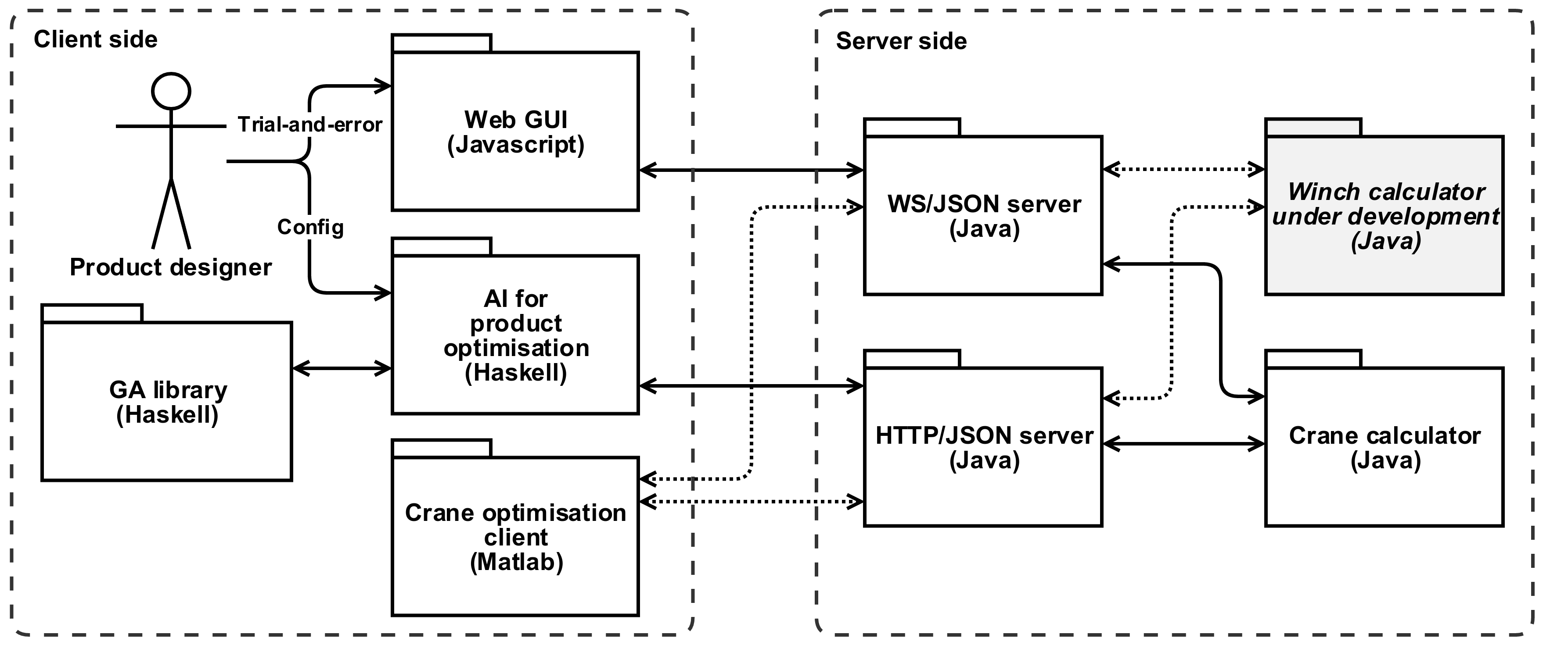
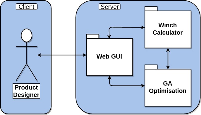
The diagram below shows a high-level overview of the software architecture of our product optimisation system.
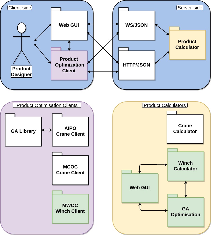
The system employs a server-client software architecture. The main component of the server is a product calculator, e.g., for offshore cranes or winches, that contains a number of different product design parameters, of which many are interdependent through electrical, hydraulic, and mechanical interactions in a highly complex, and often nonlinear, manner. Different parameter values constitute different designs of the same product. When new parameter values are set, the product calculator calculates a number of KPIs. The goal of the product designer is to determine the parameter values that yields a product design with desirable KPIs.
Using a client, the product designer can manually set the parameter values in the product calculator via two different communication interfaces:
- the Hypertext Transfer Protocol (HTTP), or
- the WebSocket (WS) protocol.
In return, the client can obtain the values of the KPIs, as well as other measures of interest, calculated by the product calculator. These bidirectional messages are transferred as JavaScript Object Notation (JSON), which is a lightweight human-readable data-interchange format.
Determining a suitable product design by manual trial-and-error is a tedious task for the product designer. Instead, one can opt to use a product optimisation client (POC) that automates this process. In addition, it may be beneficial to use a graphical user interface (GUI) both for interacting with optimisation software and with the server-side product calculator.
The design of this software framework is generic and modular. On the server side, we can develop new product calculators as long as they conform to the HTTP/JSON or WS/JSON communication interfaces and message formats that we have defined.
Likewise, on the client side, users can develop GUIs and POCs for different products as needed, again as long as they conform to said communication interfaces and message formats.
Recently, we have experimented with various client solutions and developed both a GUI and several POCs for optimisation of offshore cranes, including the Artificial Intelligence for Product Optimisation (AIPO) client written in Haskell that uses a GA for the optimisation citep{bye16}, as well as the Matlab Crane Optimisation Client (MCOC) that uses several evolutionary algorithms for the optimisation, including the GA, SA, PSO, and GWO algorithms.
Artificial Intelligence for Crane Design
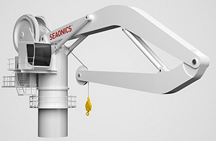
The figure below shows a Seaonics knuckleboom crane, which is one of several kinds of cranes designed and delivered by Seaonics AS.
The main components of such cranes are illustrated in the figure below:
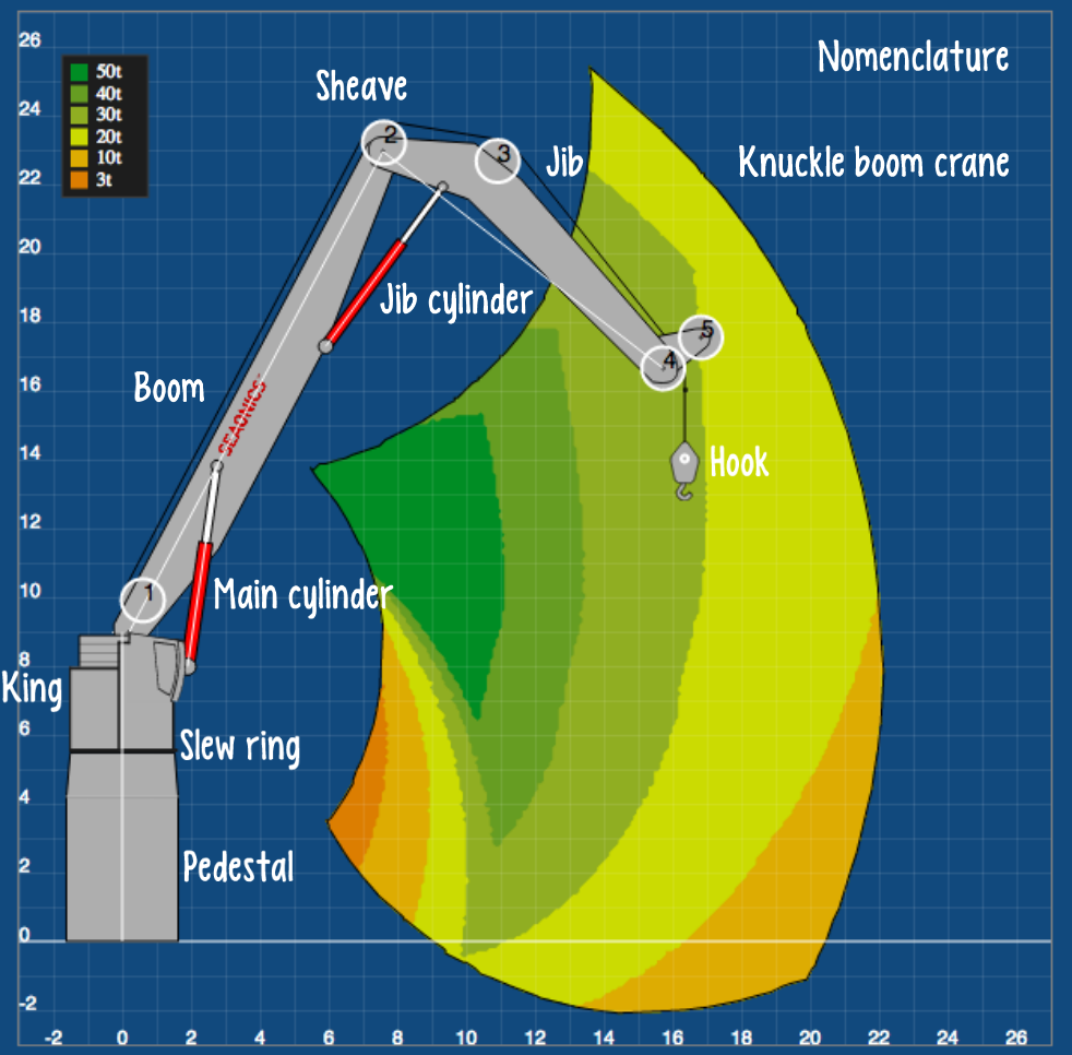
The choice of crane components and their physical properties and interrelationships determines various measures of performance of interest to the crane designer. For example, key performance indicators (KPIs) such as the desired workspace, the working load limit (WLL) and the safe working load (SWL) within that workspace; the total weight of the crane; its control system characteristics, durability, installation and operating costs; and safety concerns are all factors that the crane designer must take into account when designing a new crane. In addition, laws, regulations, and the use of design codes such as the standards provided by classification socities like DNV-GL, Lloyd’s Register Group Limited, and the American Bureau of Shipping all put constraints on the choice of design parameters.
Motivation and aim
The various models, calculations, simulations, and visualisations reported in the literature are mainly used as VP tools requiring a human to manually try and test design solutions until satisfied. For example, one may use a trial-and-error procedure to improve the traditional experience-based rule-of-thumb approaches employing pen-and-pencil or spreadsheet calculations commonly employed in the maritime industry but this method is hardly satisfactory given the large number of design parameters involved.
The findings reported in the literature typically describe various means to determine offshore crane properties and behaviour based on pre-determined design parameters, analogous to calculating the forward kinematics of a robotic arm. However, the inverse problem, namely that of choosing appropriate, possibly conflicting, values for numerous offshore crane design parameters such that some desired design criteria are satisfied, is much harder.
The aim of our two research projects is to solve this problem for respectively offshore cranes and winches by means of an intelligent CautoD software framework employing a GA for searching through the vast number of design choices and combinations until an optimised design is found. The design will inevitably involve tradeoffs and thus be Pareto optimal, which means that improving some aspect of the design will necessarily detract from another.
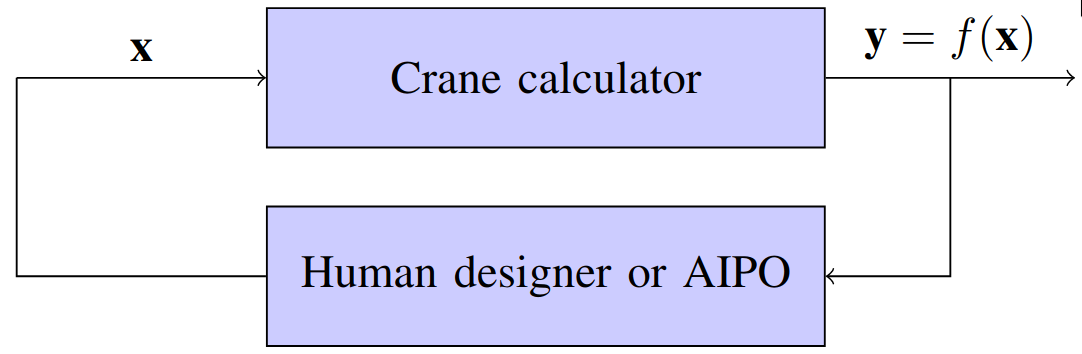
Software architecture
The main idea is to aid, or replace, a human designer using trial-and-error by an automated procedure for determining the right values for design parameters x that yields a desired design y:
Case study
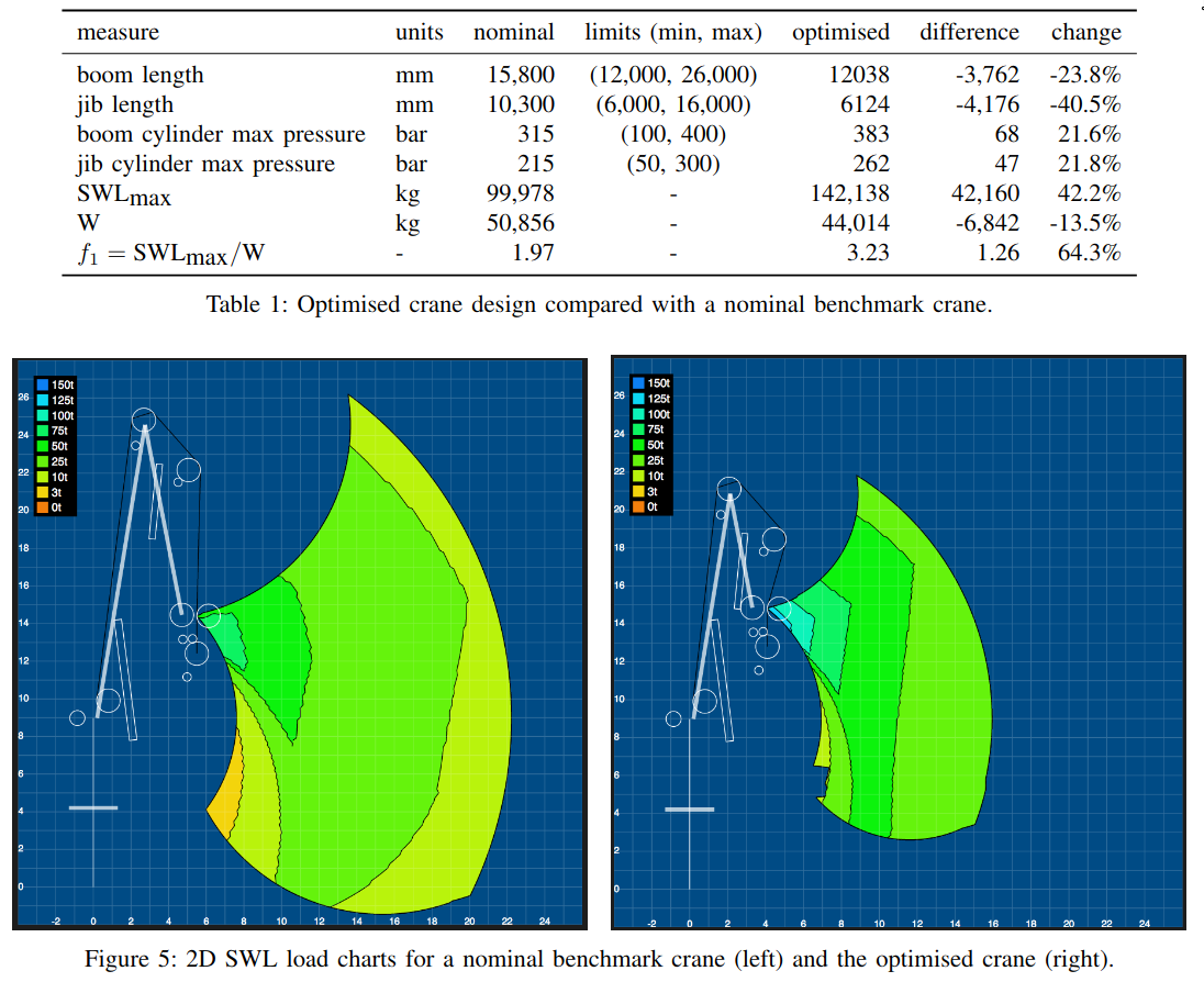
Two KPIs were chosen as components of an objective function to be optimised:
- the maximum safe working load SWLmax, and
- the total crane weight W.
The maximum SWL, on the other hand, is a measure of the maximum lifting capacity of the crane in the entire workspace. In a particular crane configuration, with the tip of the crane in a particular position of the workspace where SWL is maximum, all other configurations with the crane tip in surrounding positions will have a SWL less than or equal to the maximum SWL.
The goal of the crane optimisation was thus to maximise SWLmax while simultaneously minimising W.
Results
Artificial Intelligence for Winch Design
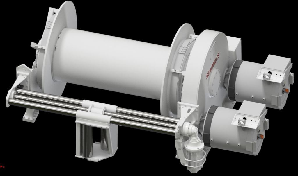
The figure below shows a winch system in the Seaonics Big Drum Trawlwinch series, which is one of several kinds of maritime winch systems offered by Seaonics AS.
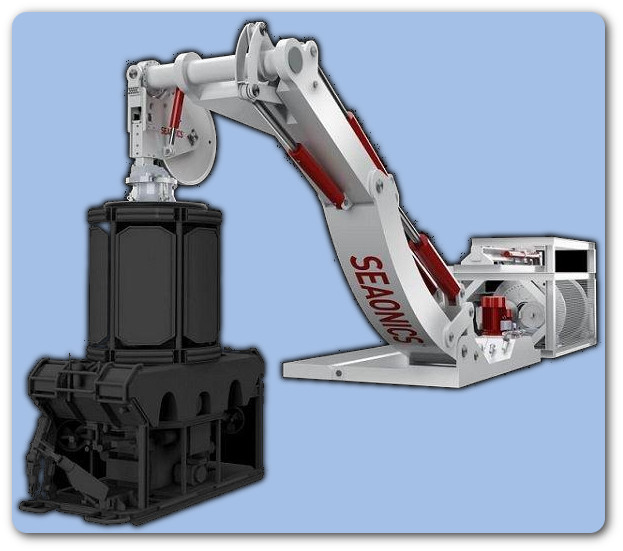
Another example of a maritime system with a winch is the Seaonics SCM-LARS shown below, a new super compact launch and recovery system (LARS) that comes with a 3000 m umbilical on an electric winch with permanent magnet (PM) motors.
In addition to trawling, maritime winches are used for anchor handling, mooring, towing, and more. The winch may at first sight appear insignificant and is an often-taken-for-granted piece of machinery, however, winches are often required to precisely monitor various operating conditions (e.g., cable payout length, speed, and tension) and are often used for features such as active motion compensation, integrated cable cleaning systems, remote control, and computer interface.
Thus, maritime winch systems are complex, come in many flavours, and consist of many different parts and components. With the advent of new technologies, major improvements in the drive systems, cable handling, safety and reliability are possible, particularly in motor and hydraulic controls.
Examples of recent relevant research include model-based control designs for offshore hydraulic winch systems, the influence of fishing grounds on trawler winch design, winch design interventions for safety and entanglement hazard prevention, analysis of trawl winches barrels deformations, and high performance winch and synthetic rope systems for workboats, tug boats, and commercial marine applications, to mention some.
In the work we present here, we focus on winches with two kinds of motors, namely electric and hydraulic. Together with the drum and the wire, these four components and their properties yield a number of design parameters that must be appropriately chosen by the designer to achieve a winch design with desired measures of performance, or key performance indicators (KPIs). Many of these parameters are dependent on each other and the winch designer must apply an iterative process to obtain a satisfactory design.
In our work on winch design, we have been mainly concerned with torque performance but emphasise the many other concerns must be taken into account by the winch designer, including adhering to laws, regulations, and the use of design codes such as the standards provided by classification socities like DNV-GL, Lloyd’s Register Group Limited, and the American Bureau of Shipping.
Motivation
Designing an optimal winch requires deep knowledge about its intended application.
For example, an optimal winch for trawling will not be optimal for heave-compensated cranes, since heave compensation will operate in a sinusoidal mode around a working area whereas trawling will require high capacity for bringing the catch on-board in a continuous operation. Also, within any one application there are usually many conflicting requirements. For instance, for trawling it is important to set the net quickly, which requires high wire velocity and a winch drum with a large inner diameter. However, when the net is full of fish, one needs high torque, which requires lower wire velocity and a smaller drum diameter.
In order to improve the versatility of the winches and improve their performance, it has become popular to make hybrid winches that employ both electrical and hydraulic motors. This makes it possible to design winches that combine some of the advantages of both electrical and hydraulic motors.
Due to the large number of design parameters, it is a difficult task to engineer a winch.
Usually this will involve rather complicated spreadsheets that are difficult to use and maintain and have very limited visualisation features.
For hybrid winches with both electric and hydraulic motors the design process can be even more complex. Finally, even with a fully functional spreadsheet, the most difficult part remains, namely finding the optimal parameters. Due to the large number of parameters, the task of improving the design through trial and error is very time consuming and difficult.
In the next sections we present our winch prototyping tool (WPT) that has support for hybrid winches and with built-in support for “automagic” parameter optimisation.
Unlike many other automatic parameter optimisation tools, this tool also support selection from predefined components, such as a catalogue of commercially available motors. Hence, designers are free to limit parameters to an interval or to a predefined set of components. Another rather unique feature is that designers can limit the scope of the component library. For example, the designers may choose to let predefined component sets such as pairs of motors and gears be lumped together as bigger units, or they may choose to have the software search for motors and gears independently of each other.
Intelligent Winch Prototyping Tool (WPT)
The intelligent WPT we present here is similar to the intelligent offshore crane prototyping tool (CPT) we have presented previously. Just as offshore cranes, winches have a large number of components and properties, with some more important than others. Implementing these parameters in a winch calculator based on detailed models of the physics involved, we are able to calculate the theoretical physical properties for a given winch design as defined by the chosen set of parameter values.
The aim of the winch designer is choose the parameter values that results in a winch design with desirable properties, usually expressed as KPIs, while simultaneously meeting requirements by laws, regulations, codes and standards. Our industrial partner, Seaonics AS, has identified a subset of the most important design parameters that the winch designer is free to experiment with. Via a web GUI (see further below), the designer can set and manually tune these design parameters, or use a GA to optimise the design based on some desired optimisation criteria. Seaonics AS has tested the WPT and the accuracy of the tool has been verified against other existing tools such as spreadsheets currently in use in the industry.
Web Graphical User Interface (GUI)
To simplify practical use of the winch calculator, we have implemented a web GUI:
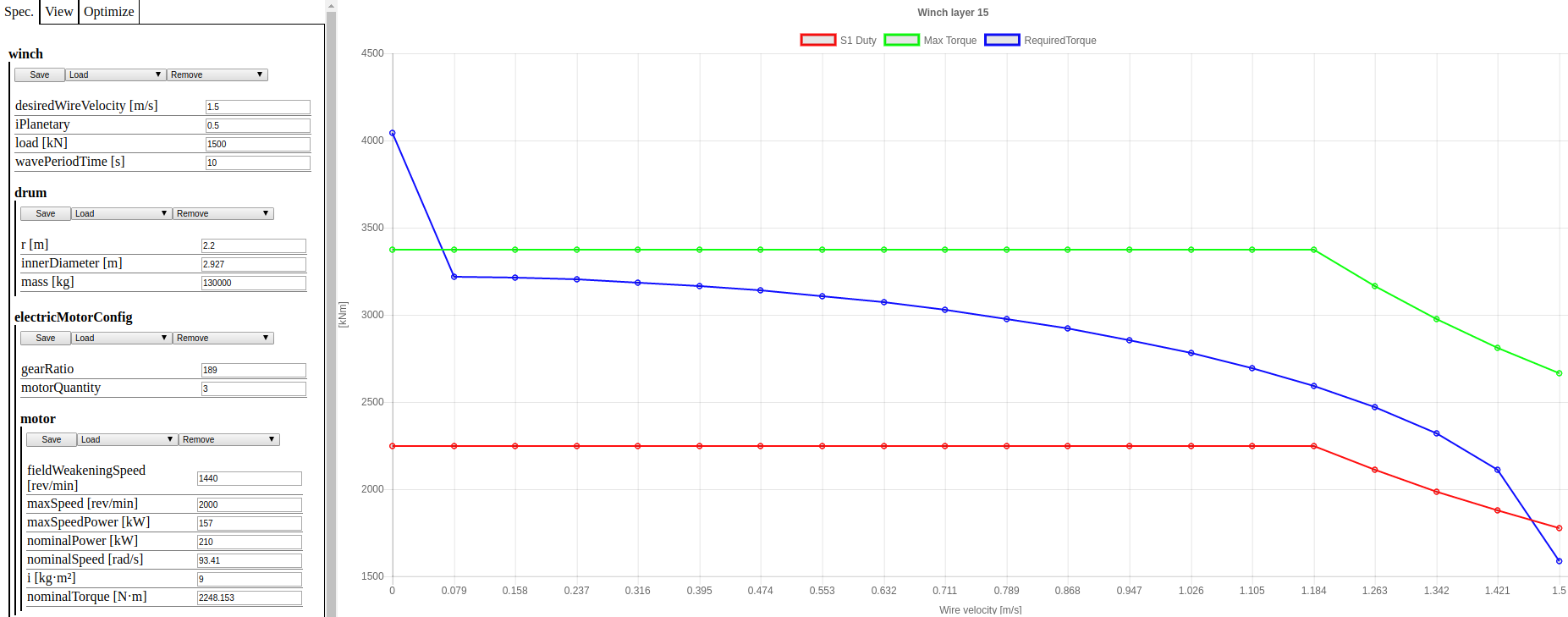
The GUI has two main panes: one for user input (left-hand pane) that allows the user to select one of three tabs: Specify, View, and Optimize; and one for displaying a graph of key torque characteristics (right-hand pane).
Under the Specify tab, the user can enter values for the winch design parameters, and observe how newly entered values will update the graphical key torque characteristics in the right-hand pane. Parameters are grouped together and categorised as belonging to one of four major components of the winch, namely the drum, the electrical motor, the hydraulic motor, or the wire. Under the View tab, the user can set the resolution (number of data points) of the graph; the total number of winch layers; and the current layer to be observed in the graph. The user can also generate a file in portable document format (PDF) that contains a plot for all the winch layers.
Under the Optimize tab, the user can use a genetic algorithm (GA) to optimise a winch design based on a user-defined objective function. To do so, the user must
- set a number of settings for the GA;
- define a suitable objective function (more details in following sections); and
- set the allowable ranges (constraints) for each design parameter (optimisation variable) to be optimised.
The right-hand pane shows graphically the S1 continuous duty cycle (one of eight duty cycle classifications (S1–S8) provided by the International Electrotechnical Commission in the IEC 60034-1 standard) torque (red), the maximum torque (green), and the required torque (blue), as functions of the wire velocity, for a given set of winch specifications and for the particular winch layer defined under the Specify and View tabs, respectively. When a parameter value changes, or after an optimisation has been run, the plots are automatically updated to reflect the effect on the three torque profiles determined by the winch calculator.
Matlab Winch Optimisation Client (MWOC)
In addition to the built-in GA in the web GUI described above, we have also implemented a Matlab Winch Optimisation Client (MWOC). The MWOC module makes use of two libraries freely available from the MathWorks File Exchange that were used for the WS/JSON interface, namely MatlabWebSocket, which is a simple library consisting of a websocket server and client for Matlab, and JSONlab, which is a toolbox to encode/decode JSON files in Matlab. For optimisation, we used a set of solvers for evolutionary optimisation algorithms available in the Global Optimization Toolbox, namely the GA Solver, the Multiobjective GA Solver, the Simulated Annealing Solver, and the Particle Swarm Solver.
Case study
As a simple case study, the main KPI that Seaonics AS is interested in is the three torque profiles that result from a given winch design, namely the S1 continuous duty cycle torque, the maximum torque, and the required torque, which are all functions of the wire velocity. The S1 torque is the maximum continuous duty cycle with constant load that the electric motors can safely operate under. The maximum torque is an upper threshold at which the electric motors can safely operate under but only for shorter periods of time. The required torque is the minimum torque required for safe operation for a given constant load.
The torque profiles are also dependent on the winch layer of interest. The number of winch layers, as well as the winch layer to be inspected, can be set in the View tab in the web GUI. Since the torque requirements of the winch increase with winch layers, it makes sense to optimise the design parameters for the outermost winch layer.
In this case study, the winch is designed with 15 layers and we optimise with respect to layer 15.
Results
The figure below shows the torque profiles from employing a GA for optimisation:
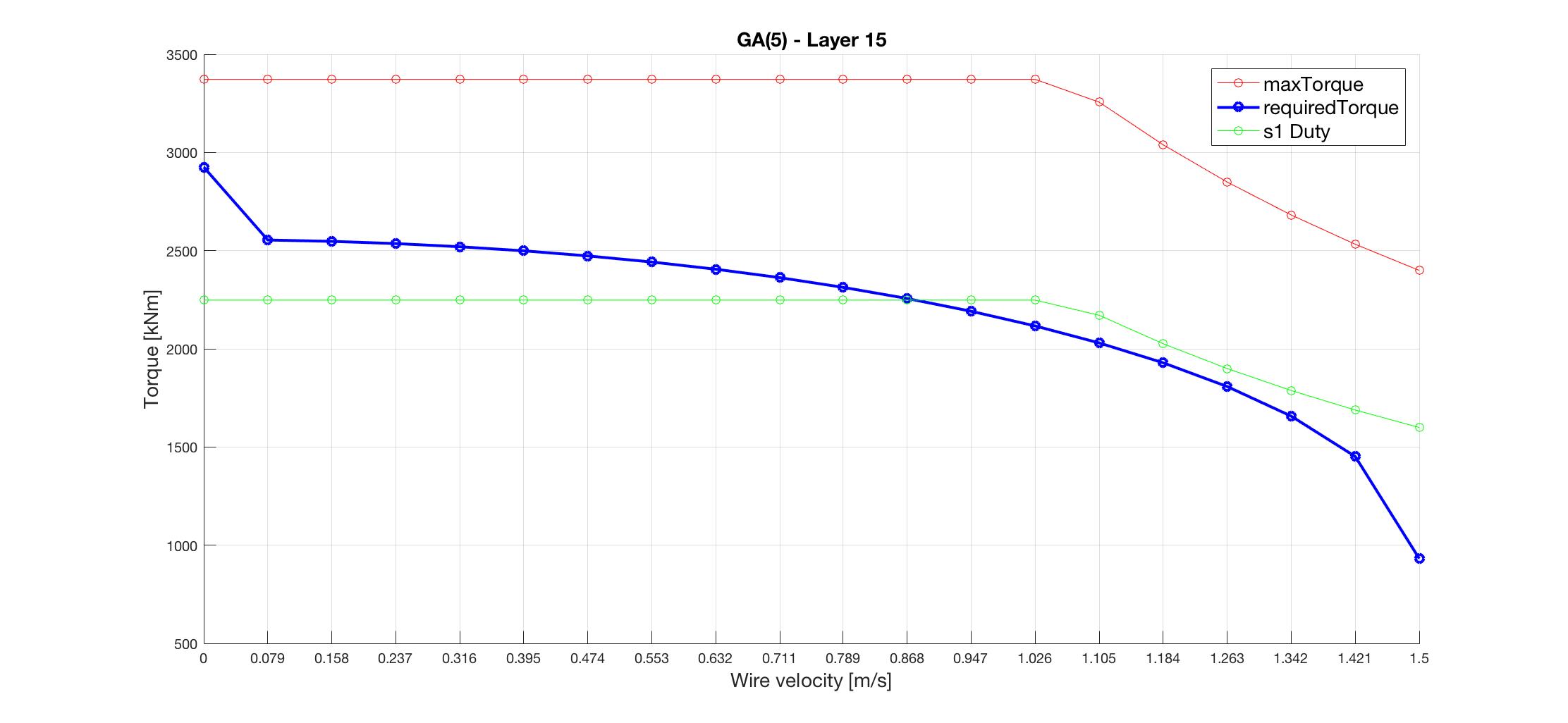
We have performed intelligent winch design by employing a set of four evolutionary optimisation algorithms; the GA, PSO, SA, and MOOGA. The algorithms are implemented in a Winch Prototyping Tool, the WPT, and in a Matlab Winch Optimisation client, the MWOC, that connects to the winch calculator in the WPT, thus demonstrating practical use of our software framework for intelligent product design optimisation.
For the case study, we set out to improve a default winch design that did not satisfy the desired performance, or KPI, as described qualitatively in a set of design guidelines.
These guidelines describe the desired relationship between the required torque, the S1 duty cycle torque, and the maximum torque, which all are functions of the wire velocity.
We have devised a cost function derived from these guidelines with the intention of using the aforementioned evolutionary algorithms to determine optimised parameter values that should result in satisfactory winch designs. Obviously, simply adding a large number of motors would result in highly proficient torque profiles. However, doing so would result in winch designs that are better than needed and also are very costly.
Intelligently, the evolutionary optimisation algorithms we have employed here are able to strike a sweet spot between the weak default winch design and too powerful winch designs that massively exceed the desired torque performance.
Our work demonstrate that employing evolutionary algorithms in our product optimisation system can be useful for CautoD of maritime equipment such as offshore winches and cranes but also for any other product for which the design can be parameterised and the design goal is to determine a suitable set of parameter values for which the resulting design satisfy some desired design criteria, or KPIs.