
This hardware architecture distributes processing across two main computing units, with sensor data synchronized through a dedicated hardware interface board.
The system is designed to separate perception processing from control operations while maintaining precise timing for sensor data acquisition.
Computing Units
- LattePanda 3 Delta (Product Page) (LP3)
- NVIDIA Jetson Orin NX 16GB Compute Module (Product Page)
- JNX42-LM carrier board (Product Page)
- Leaf Spring Kit (Product Page)
- Heatsink and FAN (Product Page)
- 2x 1TB Samsung NVMe SSD
Perception Unit - Jetson Orin NX on Auvidea JNX42
This combination of the Jetson Orin NX module with the JNX42 carrier board provides a versatile platform for deploying AI applications at the edge, suitable for use cases in robotics, industrial automation, and intelligent video analytics

Setup Guide (flashing and installing sensor drivers)
Specifications
RAM: 4GB
Storage: 1TB Samsung NVMe SSD
I/O: Product page
Control Unit - LattePanda 3 Delta (LP3)
The LattePanda 3 Delta is a compact single-board computer (SBC) designed to deliver robust performance for a variety of applications, including IoT development, robotics, and edge computing.

Specifications
RAM: 8GB LPDDR4
Storage: 1TB Samsung NVMe SSD
I/O: Product page
Sensor Units
- 2x StereoLabs ZED X Stereo Cameras (Product Page)
- Ouster OS1 LiDAR (Product Page)
- Sensonor STIM300 IMU (Product Page)
- SentiSystems Dual GNSS Receiver with 2x ZED-F9P GNSS modules (Product Page)
Camera
StereoLabs ZED X Stereo Cameras
The ZED X is an advanced AI stereo camera, designed to enhance robotic and spatial perception applications. It features an IMU with vibration resistance which offers motion tracking capabilities. It is used with a Stereo ZED Link Capture Card.

Specifications
Stereo baseline: 120mm
Lens focal length: 2.2mm
Field of view (FoV): 110 (H) x 80 (V) x 120° (D)
Depth range: 0.3m -20m
Shutter type: Global
Resolution: 1920x1200, 1920x1080, 960x600
Frames per second: 15, 30, 60 or 120 (120 fps only at 960x600)
Connector: FAKRA Z plug
NB! The camera delivers video feeds from both cameras at once. The main camera with rectified images is the left camera. SDK only compatible with CUDA
Light Detection and Ranging - LiDAR
Ouster OS1
The Ouster OS1 is a high-resolution, mid-range lidar sensor.

Specifications
Minimum range: 0.5m
Max range: 170m @ >90% detection probability, 100 klx sunlight
Rotation rate: 10Hz or 20Hz
Field of view: Vertical: 42.4° ± 1.0° Horizontal: 360°
Resolution: Vertical: ±0.01° Horizontal: ±0.01°
Points per second: 1,310,720 @32ch., 2,621,440 @64ch., 5,242,880 @128ch.
Connector: Eaton UTGX 12 pin female
Inertial Measurement Unit - IMU
Safran SensoNor STIM300
The STIM300 is a compact, tactical-grade, high-performance Inertial Measurement Unit. Itintegrates three MEMS gyroscopes, three high-stability accelerometers, and three inclinometers within a lightweight package. Also gives temperature. It is configured with software developed by Safran. Configuration software NB! A specialized cable sold by Safran is needed to configure the IMU.

Specifications
Gyroscope Range & Resolution: ± 400°/s, 0.22°/h
Gyro. Bias instability: 0.3°/h
Gyro. Drift: 0.15°/√h
Accelerometer Range & Resolution: ± 10g, 1.9µg
Acc. Bias instability: 0.04mg
Acc. Drift: 0.07m/s/√h
Sample rate: 2000Hz (configureable)
Connector: MICRO-D 15 pin female
Global Navigation Satellite System - GNSS
The u-blox ZED-F9P is a high-precision GNSS module that delivers centimeter-level accuracy. Supports real-time kinematic (RTK) positioning. Gathers satellite information from almost all constellations. The SentiSystems Dual GNSS Receiver integrates two u-blox ZED-F9P modules with connections for two antennas. It is used with the Sentiboard v1.3. The u-blox ZED-F9P modules is configured with software developed by u-blox. Configuration software. NB! With two modules we can calculate heading
SentiSystems Dual GNSS Receiver with u-blox ZED-F9P module

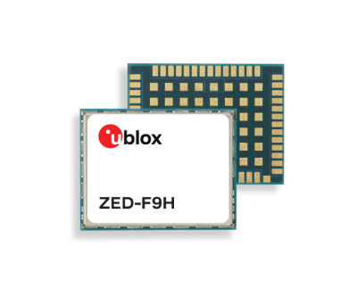
Specifications
Minimum number of Satellites Used: 4
Positioning Accuracy: 0.01 m + 1 ppm CEP (depending on baseline length and weather conditions )
Navigation rate: Up to 20Hz
Cold start time: 24s
Antenna Type: External. Antenna
Connectors: SMA female (antenna), USB-C (configuration), Samtec MicroMate S1SD 10-Pin (data)
Hardware Synchronization
- SentiBoard v1.3
- Uses GNSS/GPS time signal as reference for synchronization, more on that at Time Synchronization Overview

SentiBoard v1.3 Configuration
Before properly setting up and configuring the SentiBoard follow this guide: SentiBoard v1.3 setup guide.
To properly read out sensor data from the ports the format of the data package must be studied to ensure right formatting in terms of data byte lengths, baud rates and synchronization ids.
| Sensor Port Configuration | |||||||
|---|---|---|---|---|---|---|---|
| Port Name | Com. Standard | Sync. ID | Baud Rate | Data Length Bytes | Data Messages | Sensor Data Format Documentation | Sensor Type |
| U1 | UART 8N1 | 0xB5 0x62 | 921600 | 64, 28, 92, 64, 16 | UBX-NAV: COV, HPPOSECEF, PVT, RELPOSNED and STATUS | u-blox HPG 1.32 interface description - Section 3.15.(2/6/13/14/20) | ZED-F9P (HPG 1.32) - GNSS |
| U2 | UART 8N1 | 0xB5 0x62 | 921600 | 64, 28, 92, 64, 16 | UBX-NAV: COV, HPPOSECEF, PVT, RELPOSNED and STATUS | u-blox HPG 1.32 interface description - Section 3.15.(2/6/13/14/20) | ZED-F9P (HPG 1.32)- GNSS |
| R4 | RS-422 8N1 | 0x91 | 921600 | 28 | Rate and acceleration (RA) | STIM300 datagram description - Section 5.5.6 | Stim300 - IMU |
Unknown User (lctran) todo triggers
Communication
TODO: Unknown User (lctran) and maybe Unknown User (benjabj)
Power Distribution
| Component | Input Voltage (V) | Power (W) | Notes |
|---|---|---|---|
| Computing Units | |||
| NVIDIA Jetson Orin NX (Not on carrier board) | 5-20V | 10-20W | Orin NX Datasheet |
| LattePanda 3 Delta | 11-15V | 24W minimum | LP3 power documentation |
| Sensor Units | |||
| Ouster OS1 LiDAR | 12V or 24V | 20W minimum | Ouster OS1 datasheet |
| 2x StereoLabs ZED X Stereo Cameras | 14-19V | Supplied by Duo card | Powered by capture card. NB! (12V has worked before, but other voltages are specified) |
| StereoLabs Zed Link Duo Card | 14-19V | 20W minimum | ZED Link Duo Capture Card datasheet. NB! (12V has worked before, but other voltages are specified) |
| Sensonor STIM300 IMU | 5V | 2W maximum | STIM300 IMU Datasheet |
| Sentisystems Dual GNSS receiver board | 5V | N/A | Dual GNSS guide Powered by SentiBoard v1.3 |
| 2x SignalPlus GPS/GNSS Antenna | 3-5.5V | 0.25W maximum | Antenna product page |
| Integration Hardware | |||
| Sentisystems SentiBoard v1.3 | 5V | N/A | SentiBoard v1.3 documentation |
| Auvidea JNX42 carrier board | 12V | 1W | JNX42 product brief. The Jetson Orin NX is mounted on this board |
| Teltonika RUTX50 Industrial 5G Router | 9-50V | 18W maximum | |
| Taoglas MA114 5G and GNSS antenna | 1.8-5.5V | 10W maximum | |
| Propulsion and Power System | |||
| 2x BlueRobotics M200 thruster | 7-20V | 390W (@16V draws 24A) | |
| 2x BlueRobotics Basic ESC 500 (BlueBoat edition) | 7-26V | N/A | ESC 500 product page. Can also serve as a battery which outputs 5V@4A |
| Traco Power TEP 150-2412WI | 9-36V | 150W | TEP 150-2412WI product page. DC/DC converter. Outputs 12V@12.5A. Used as main power source for electronics inside the WE |
| Traco Power THN 15-2411WIR | 9-36V | 30W maximum | THN 30-2412WIR product page. DC/DC converter. Outputs 12V@2.5A. Used for powering fans, 5G router and LattePanda. |
| 2x BlueRobotics Lithium-ion Battery 14.8V 18Ah | N/A | N/A | Battery product page. Nom. output 14.8V, can be fully charged to output 16.2V |
| Auxiliary Hardware | |||
| 3x Noctua NF-A6x25 FLX | 12V | 1.44W maximum | NF-A6x25 FLX datasheet. NB! (Power is read from box, other wattages are stated online) |
| BotBlox GigaBlox switch | 5.1-60V | 260-1100mW | GigaBlox documentation. The switch is unmanaged |
| BlueRobotics NavLight | 5-12V | 2.5W | |
| Xbox Elite Controller Series | N/A | N/A | |
Physical Integration
Watertight enclosure (WE)
The computing units and accompanying power rails, electrical cabling and fans are housed in a waterproof Pelican Air Case which has been modified for cable interfaces for GNSS and image data.
Internal wire diagram

LIDAR mounting structure
In order to mount to OS1- LiDAR to the BlueBoat, a supporting structure and accompanying adapters has to be secured to the vessel.
3D- printed parts
| Rigid mount | Rotating mount L | Rotating mount R | Rigid sock L | Rigid sock R | Rotating sock L | Rotating sock R | Lidar platform | |
|---|---|---|---|---|---|---|---|---|
|
|
|
|
|
|
|
| |
| Quantity: 2 | Quantity: 1 | Quantity: 1 | Quantity: 1 | Quantity: 1 | Quantity: 1 | Quantity: 1 | Quantity: 1 | |
| STL file | STL file | STL file | STL file | STL file | STL file | STL file | STL file |


These parts were printed using a Bambu Lab X1C printer.
The parts were sliced using Bambu Studio.
Slicer settings:
Strength
- Wall loops: 5
Support
- Enable support: Yes
- Type: tree(auto)
- Style: Tree Hybrid
We used glass fiber reinforced PA6(Nylon 6) to print the parts.
In order to keep the rigidity and structural integrity of the finished print, it is advisable to dry the filament in an applicable filament dryer.
Recommended drying settings:
- 68 degrees celcius
- 48 hours
Manufactured and 3rd party parts
| Lidar plate (anodized aluminium) | Carbon fiber tubes |
|---|---|
|
|
| Quantity: 1 | Length: 2m, Thickness: 2mm, Inner Ø: 12mm, Outer Ø: 16mm |
| STL file | Link |


Assembly instructions:
1. Fastening the mounts to the boat

Parts needed:
2x rigid mounts
1x rotating mount L
1x rotating mount R
16x M6 screws (max 8mm in length)
_________________________________________________________________________________________________________________________
Fasten the two rigid mounts using 8x M6 screws in the front of the vessel indicated by the red dotted circles.
Fasten the two rotating mounts using 8x M6 screws in the back of the vessel indicated by the red dotted circles.
_________________________________________________________________________________________________________________________
2. Cutting the carbon rods
Equipment needed:
1x Machine capable of cutting carbon rods.
_________________________________________________________________________________________________________________________
The carbon rod should be cut into 4x lengths of 452mms. The tubes will act as an interface between the socks and the lidar platform.
_________________________________________________________________________________________________________________________
3. Using epoxy to fasten the lidar platform to the rigid and rotating socks.
Parts needed:
1x rigid sock L
1x rigid sock R
1x rotating sock L
1x rotation sock R
1x lidar platform
Equipment needed:
1x Epoxy
_________________________________________________________________________________________________________________________
Apply epoxy in both ends of the 4x lengths of carbon tubes. Attach one variant of socks in the end of the tubes. The other end should be attached to hole in the lidar platform. The structure should then be placed on the rigid mounts fastened in step 1. Attach one M10 screw trough the sock and rigid mount with a locking nut. Make sure that alle the glued parts are pressed together and let it dry.
_________________________________________________________________________________________________________________________
Camera mounting structure
In order to mount the ZED-X camera modules to the BlueBoat, a rigid mount is necessary.
3D- printed parts
| Modifiable camera mount | |
|---|---|
| |
| Quantity: 2 | |
| STL file |

This part were printed using a Bambu Lab X1C printer.
The part was sliced using Bambu Studio.
Slicer settings:
Strength
- Wall loops: 5
Support
- Enable support: Yes
- Type: tree(auto)
- Style: Tree Hybrid
Orientation
- It is advisible to print the camera mount on its side for additional rigidity. (The short side of the platform should be touching the printing bed)
We used glass fiber reinforced PA6(Nylon 6) to print the part.
Cables and connections - WIP
Custom cables were manufactured/ordered to meet the demands of the marine environment. The cables needed to withstand a saltwater environment and the connections to the watertight enclosure needed to be sealed with bulkheads to prevent water seeping in. Additional cables for transferring data inside the WE were also made
| Sensor Connections | ||||||
|---|---|---|---|---|---|---|
| Usage | Type | Connector 1 | Connector 2 | Length | Quantity | Note |
Cameras - WE | RG-174 | FAKRA Z jack | TNC male | 125 cm | 2 | Customized order |
WE - Capture card | RG-174 | TNC female bulkhead | FAKRA Z plug | 10 cm | 2 | Customized order. The bulkhead is part of the cable |
| GNSS antennas - WE | LMR-240 | TNC male | TNC male | 36 in | 2 | Customized order |
| WE - GNSS board | RG-405 | TNC female bulkhead | SMA male | 12 in | 2 | Customized order |
| LiDAR - WE | Ethernet mod. | Eaton UTGX 12 pin | Eaton UTGX bulkhead 12 pin | TBD | 1 | Assembled in TURlab. CAT7 |
| WE - Network switch | Ethernet mod. | UTGX 12 pin | Picoblade female receptacle 8 pin | TBD | 1 | Assembled in TURlab. CAT7 |
| GNSS board - SentiBoard v1.3 | UART | S1SD 10-Pin | S1SD 10-Pin | TBD | 2 | Bought. Samtec MicroMate |
| LP3 - SentiBoard v1.3 | USB | USB-A | MicroUSB | TBD | 1 | Assembled in TURlab |
| IMU - SentiBoard v1.3 | RS-422 | MICRO-D 15 Pin | S1SD 10-Pin | TBD | 1 | Assembled in TURlab. IMU connector. Samtec MicroMate |
Crosstube Connections | ||||||
| Port hull - WE | Ethernet | RJ45 | RJ45 | TBD | 1 | Assembled in TURlab. Extra for future data transmissions/signals. 8 wires. CAT7 |
| Port hull - WE | Ethernet mod. | Molex MicroFit male | Molex SL male | TBD | 1 | Assembled in TURlab. 2 of 8 wires used for thruster PWM ESC. CAT7 |
| WE - Starboard hull | Ethernet mod. | Molex SL male | Molex MicroFit male | TBD | 1 | Assembled in TURlab. All wires used for thruster PWM ESC, NavLight LED and PowerSense module signals. CAT7 |
| WE - Starboard hull | Ethernet | RJ45 | RJ45 | TBD | 2 | Assembled in TURlab. Extra for future data transmissions/signals. 8 wires. CAT7 |
| WE - Starboard hull | Power | XT90 female | XT90 male | TBD | 1 | Assembled in TURlab. Used 8 AWG cable, XT90 spec. is for 10 AWG. Solder connection may be lackluster |
LIDAR cable wire diagram

Power Sensing Connector Mapping
- Red → Not connected
- Green → Not connected
- Blue → Current Sensing
- White → Voltage Sensing
- Yellow → Ground
- Black → Ground
Masteren nærmer seg slutten. Søvnløs periode i det siste. Nå blir det litt fri
